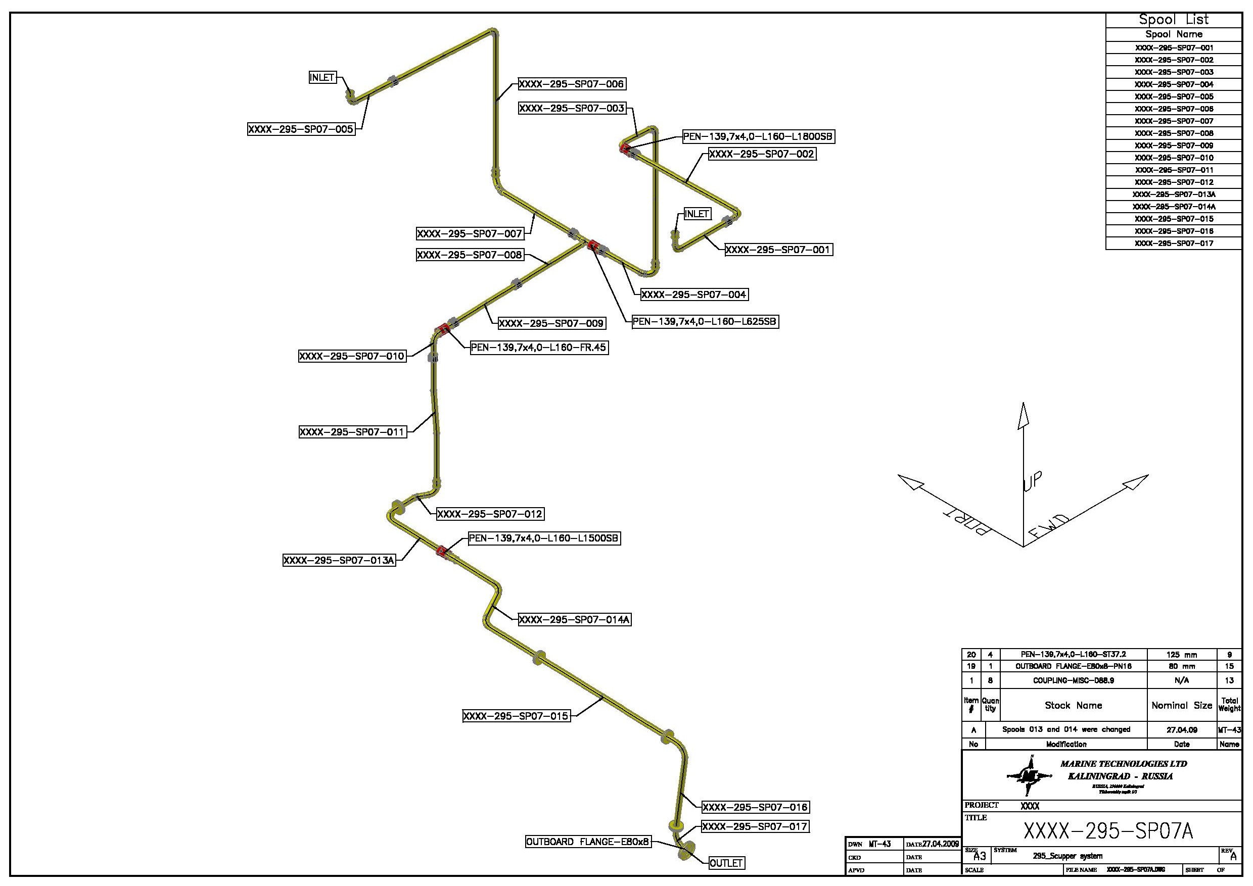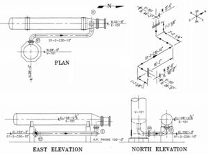

These are the points where the piping will change direction. Locate the fittings such as tees and elbows. Refer to the drawing legend to understand the meaning of each line. Isometric drawings show the size and type of pipe used in the system.

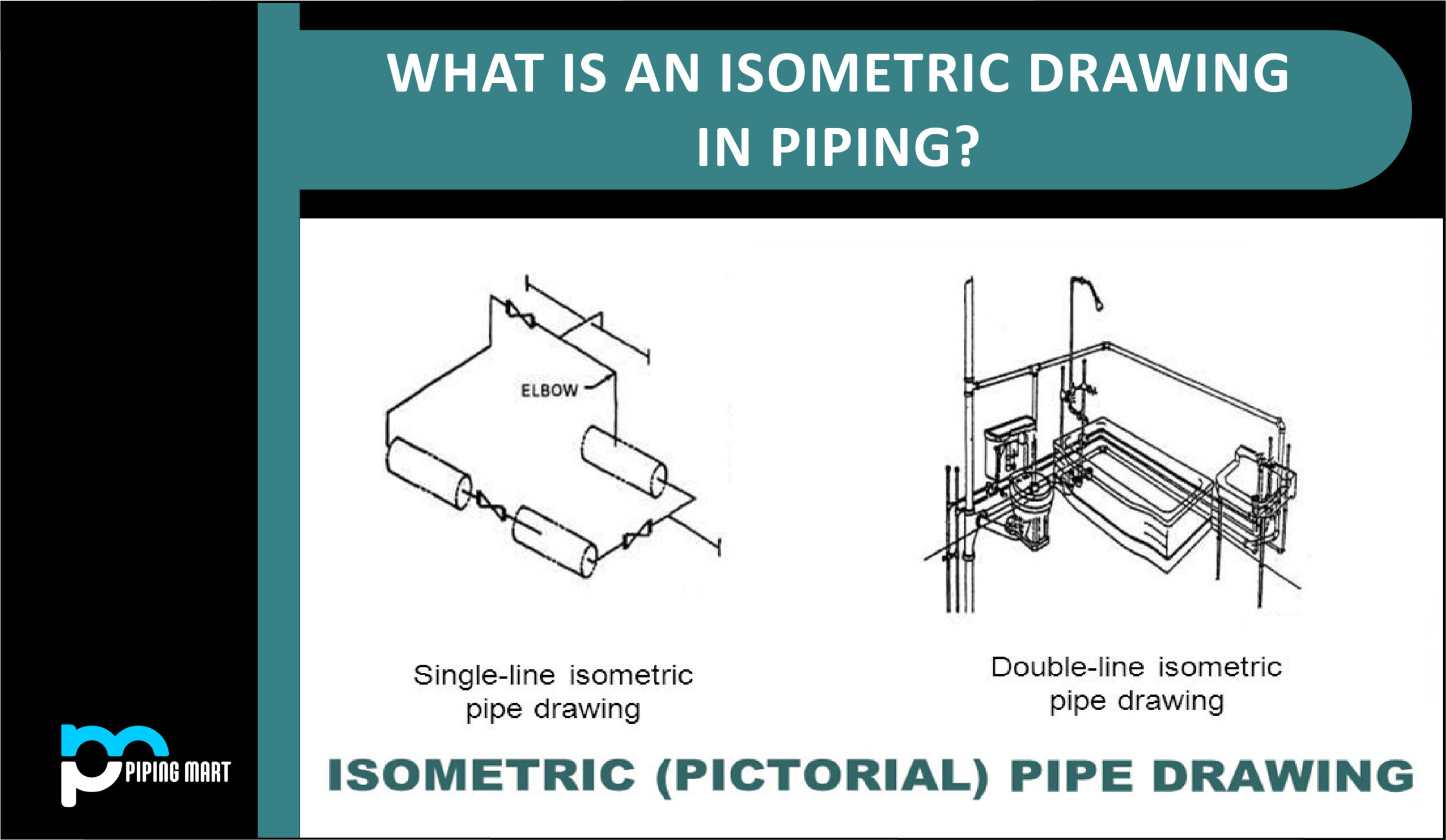
With the 'Isometric to Standard' type transposition the result can often be visualized as an offset view from overhead, where the vertical lines can still be seen. Identify the pipe size and material used. Piping Isometric drawing is an isometric representation of single. This is to avoid any confusion caused by nodes being placed over the top of other nodes or pipes. n this video we will learn how to easy read pipe isometrics, Pipefitters, Isometric drawing, pipe drawing, piping isometric drawing, how to read pipe drawi. ABOUT THIS VIDEO PIPING - HOW TO READ ISOMETRIC DRAWING FOR PIPING ENGINEER ,PIPE FITTER. When clicking the ISO Mode On/Off Toggle button to transpose from isometric view to a 'flattened' standard view, any vertical lines from the isometric view will be drawn at 45 degrees. Selecting either of these options will change the display of all tanks and end pressure on the isometric view. The drawing menu provides options to display an ‘Isometric tank view from the left’ or to display an ‘Isometric tank view from the right’. Fortunately, most modern piping programssuch as the Plant 3D toolsetautomatically generate an isometric drawing based on the 3D model. Tanks and end-pressure nodes will also be displayed in the isometric plane. When the isometric drawing mode has been selected Pipe Flow Expert will show fittings, valves, components, control valves and pumps in the isometric plane which follows the associated pipe direction. Users can easily switch between these using the ISO Mode On/Off Toggle button.

Pipe Flow Expert has two drawing modes, standard (‘flattened’) view and isometric view.


 0 kommentar(er)
